
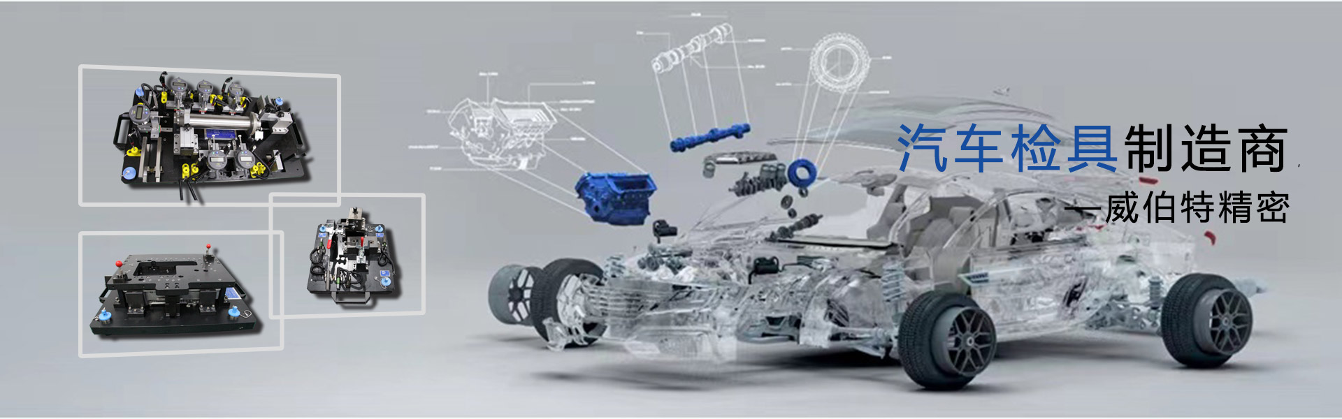
工具和夹具检具设计简介
工具和固定装置简介检具设计 一、定义:工具-顾名思义,它是专门设计和制造的辅助机械零件,模具,工具,固定装置,其设计旨在确保特定机械零件或零件的顺利进行。整机批量生产和制造过程,检查工具或设备,即机械制造过程的设备。 (用于测试产品组件或整机性能的检查工具以及用于关键零件的尺寸或形状检查工具属于一流工具,由产品设计师设计,检查部门负责保管。为了提高生产效率,促进加工并确保质量,所使用的工具属于过程工程师设计的辅助工具,并且由生产部门负责保持。)夹具专用的机械机构或用于将工件夹紧在机械中的组件制造以确保准确可靠地执行加工或装配过程。 (通常由过程工程师设计)检查固定装置-专门设计用于满足特殊零件的尺寸检测或形状确认以及整个机器性能测试的工具,机械零件或测试设备。 (绝大多数是由过程工程师设计的,而少数是由设计师设计的。)由于工具,固定装置和检查工具通常是为特定产品或零件加工步骤设计的,因此它们基本上是一件生产的,用途不同,而且用途更多结构体。很难在一份讲义中进行解释,因此本讲义将不会详细讨论结构设计,而是将重点放在夹具的技术基础,设计思路和设计案例上检具设计。至于模具(例如橡胶模具,注塑模具),吹塑模具,泡罩模具,滚塑模具,挤压模具,压铸模具,冲压模具(冲孔模具,成型模具,弯曲模具,修整模具,成型模具等)冷挤压模具,粉末冶金模具,失蜡铸造的蜡模等)。其设计方法是独立的,在本文中将不再讨论。
二、工装和夹具检具设计与机械产品设计之间的区别:机械产品设计摘要:由于它是“产品”,因此通常进入大规模生产以满足市场需求,因此该产品应遵循并满足设计要求。机器设计大纲(由市场研究人员和产品设计师共同制定),详细细分1.在满足总体机器大纲的要求(成本控制,产品功能,使用寿命,工作环境,空间位置和机器中零件的互连,机器的安装空间,人体工程学要求,机器重量,产品生产零件的材料,尺寸,形状和表面粗糙度是在数量预测,环境保护,安全,维护等前提下设计的在选择热处理和表面处理方案时,重要部分还必须考虑因素,例如检查方法,运输离子和包装。 2.根据整机的成本要求,全面权衡零件设计的材料选择,热处理表面处理的设计及相关考虑因素。 3.根据整机的成本要求,零件的批量大小和加工设备的容量,请考虑零件形状和加工方法之间的平衡。 4.重要部件需要考虑必要的测试方法和技术条件(专用工具,原型等)。 5.零件设计应考虑到组装和拆卸的简便性(即,有足够的拆卸空间,应尽可能使用通用工具并符合人体工程学设计)。 6.考虑安全性,可靠性和环境保护的要求(防火,人身安全,绝缘等级,重金属危害等)。 7.有必要考虑归纳和标准化的要求(尽可能借用可借用的零件,并在选择材料时尽可能使用现有的品种或可销售的品种,并尝试使用现有的品种。规格,测试方法和技术条件(表面处理,热处理,粗糙度)等)尝试使用标准的传统方法或要求。
8。对于批量生产的零件,应考虑材料的可加工性。 9.必须考虑产品的包装和运输条件。工装,夹具检具设计摘要:工装,夹具和检查工具用于提高机械产品的批量生产效率并确保机械产品的质量稳定性,从而达到降低产品生产成本的目的。因此,工具,固定装置和检查工具的设计和制造必须无条件地遵守此目的。工具,固定装置和检查工具通常以单件和成套的方式生产,但是使用时间通常较长。模具加工主要考虑使用寿命和维护条件。夹具主要被认为是易于使用,安全,高效和可靠的。检查工具主要考虑便利性,可靠性和便利性。鉴于上述原因,工具,固定装置和检查工具的成本问题应该让位于安全性,高效率,可靠性,寿命和易用性。由于设计原因,请尝试使用成熟的标准零件(例如导柱,导套,紧固件),弹簧,五金件,液压缸,液压缸,标准模具底座,快速卡盘等)。主要零件的设计应仔细设计,以匹配金属材料和热处理类型(例如淬火和回火,高频,渗碳和淬火,渗氮和淬火)以及硬度的选择。特别地,应考虑防止热处理后的零件变形。摩擦部件应考虑硬度匹配和必要的润滑措施。表面处理应根据零件的功能(镀锌,镀镍,光铬镀层,阳极氧化,硬质阳极氧化,导电性阳极氧化,硬铬镀层,渗色等)仔细设计涂层的厚度和类型。
三、工具和固定装置检具设计人员需求的技术基础。工装,夹具和检查工装设计的技术基础是基于丰富的实践经验的机械制造和加工技术知识,熟悉各种加工方法的特性,在常用量具的应用中,如果看到零件,您可以立即反映出用于制造零件的方法,什么加工步骤以及用于测试的测量工具或设备。工具,固定装置和检查工具的设计者还应该具有机械传动,气动和液压传动的一定知识,并且能够熟练使用各种标准零件和通用产品样品。只有这样,才能设计出满足实际需求的产品。工具和夹紧一个不了解塑料材料特性,注塑技术和注塑机,不了解金属材料特性和切削加工特性,不了解热处理表面处理应用的人,我们几乎无法想象他可以独立设计一个合理且适用的注塑模具。不懂手工钣金加工的人,不懂钣金表面处理方法的人,不熟悉金属材料焊接知识的人自动检具,不懂切割工艺的人,不熟悉热处理工艺的应用,不了解金属材料的特性,不了解冲压机的工作原理的人,我们很难想象他能设计出合格的冲压模具。不熟悉各种切割机床的操作和加工特性的人,不了解加工零件的定位的人,不具备基本钳工技能的人,不了解基准的概念和六点定位原理,不了解使用焊接方法的人,不了解常用硬件零件的应用的人,不了解机械装配的人,不了解热的表面处理的人处理,无法设计可靠,方便的固定装置和专用工具。
没有使用过常用测量工具和测量设备的经验的人,没有钳工经验的人,不了解表面处理识别过程,没有机械零件以及整体设计和加工的人机。基准的加工和测量对于具有基准概念的人来说,不可能设计出方便,可靠和准确的特殊测量夹具。总之,设计合格的工具,固定装置和检查工具需要丰富的实际生产经验。采取捷径的任何想法都是不现实的,并且只能诚实地向生产线中经验丰富的工程师和工人学习。能够忍受艰苦,努力工作(亲自操作,模拟设计和做笔记),认真思考,善于总结,并渴望满足生产需求。只有考虑到工人,您才能成长为合格的模具设计师。四、工具,夹具的基本要点,检具设计机械零件的夹紧方法直接对准夹紧件,效率低,对准精度高;适用于单件,小批量和简单形状的工件。下图中的四爪卡盘本身是一种夹具,但是通用夹具。千分表测量头千分表将千分表测量头放在工件的圆周面上,将变速箱置于空档,并在工件的旋转中心与中心不重合的情况下用手旋转四爪卡盘机床四爪卡盘的指针时针指示器的指针将跳动。此时,相对于卡盘的中心调整四个卡爪的位置。及时转动卡盘以观察百分表的指针,直到指针基本上没有跳动为止。此时,工件的旋转中心与机床卡的圆盘的旋转中心基本重合,可以开始车削加工。
工件圆周面上的四爪卡盘千分表测量头带动刨头以低速向前移动。将百分表测量头轻轻地压在工件的侧面,并继续调整工件的位置,以使工件的侧面尽可能地靠近撞锤。运动方向是平行的。一旦达到了并行性要求,百分表指示器的指针应处于静态或仅当柱塞往复运动时略微摇动。此时,工件加工之前的调整工作。划线,对准和夹紧具有通用性,但效率低,精度低;适用于单件,小批量和复杂形状的铸件。将标记针对准红线,将变速箱置于空档,用手旋转卡盘,观察针尖与红线的重合,并分别调整四个卡爪相对于卡盘中心的位置,直到卡盘旋转一次时针尖始终与卡盘的中心对齐。红线基本重合。此时,工件的旋转中心与机械卡盘的旋转中心基本重合,从而可以开始车削加工。钳工绘制的校正线是将衬里的工件放置在机床的工作面上,并使用划针检查校正线与工作台平面之间的平行度,并使用垫片对工件进行调整。工件底面要根据实际情况。直到针用于绕工件一次且针的尖端始终与校正线重合之前的工件高度。此时,工件的毛边裕度相对均匀。夹具的夹持操作简单,高效,易于保证加工精度。适用于通过齿轮定位心轴夹具加工的各种生产类型。将夹具安装在开槽台上,然后将齿轮一个接一个地安装到夹具中并拧紧。齿轮整形。零件在夹具中定位后不移动的原理是选择夹紧力的方向指向定位基准(第一基准),并且夹紧力的大小应足以平衡其他力的影响并且不会导致零件在加工过程中移动。
将零件放置在夹具中后不变形的原理。在夹紧力的作用下,零件不会在加工过程中变形,这是精度所不允许的。您必须选择合适的夹紧位置并调节压板和零件。在接触状态下,施加适当的按压力。将零件放置在固定装置中后的非振动原理可确保支撑和夹紧系统的刚性。夹紧位置应尽可能靠近零件的加工区域,以免零件和夹紧系统振动。一般而言,用于粗加工的夹具应选择较大的夹紧力,主要考虑零件的不运动原理,对于精加工用的夹具应选择较小的夹紧力,主要考虑非零件的变形和非变形。振动原理。基准的概念用于确定零件上其他点,线和面的位置所基于的那些设计基准。设计图上使用的基准是设计基准。 (图片)过程基准在处理,测量和组装过程中使用的基准。定位基准是在加工过程中用于工件定位的基准,称为定位基准。 (图片)表面是工件的定位基准。定位基准分为:a,粗基准b,精基准c,辅助基准d,主基准e,附加基准测量基准。组装基准用于确定组装期间产品中零件或组件的相对位置所采用的基准。4、六点定位定位是机加工中极为重要的问题。必须深刻理解和牢牢把握定位原理,熟悉常用的定位方法。深入了解定位不足和定位过度的概念,并正确分析和处理与定位不足和定位过度有关的问题。
深入了解定位误差的概念,并能够正确计算定位误差。六点定位原理任何未定位的工件在空间直角坐标系中都具有六个自由度。工件定位的任务是根据加工要求限制工件的全部或部分自由度。工件的六点定位原理是指使用六个支撑点来限制工件的六个自由度,以便可以将工件定位在空间中。轴上的台阶是齿轮装配基准的方法。上图显示了工件在空间中的自由度和工件的六点定位5、定位和夹紧之间的差异加工中的自由度是指工件在空间中的位置的不确定性。在此必须特别注意以区别定位和夹紧的概念。一旦夹紧工件,就不能改变其空间位置,但这并不意味着其空间位置是特定位置。夹紧是为了确保工件的位置不会因外力而改变。例如,将板状工件放置在平面磨床的磁性工作台上,并在旋转磁性开关之后,将工件夹紧并固定其位置。但是,不确定将工件放置在工作台上的哪个位置。它可以放置在位置2或位置2。六点定位原理中“点”的含义是限制工件自由度的元素,不应机械地解释为接触点。 。例如,如下图所示的板状工件被放置在工作台上,并且工件以有限的自由度被限制为三点定位。实际上,工件和工作台之间可能有多个接触点。6、工件应限制多少自由度?需要限制哪些自由度?这完全取决于加工技术要求。
上图a显示了铣削长方体工件上表面的过程。需要保持方向上的高度尺寸以及上平面和底平面之间的平行度,因此仅需要一个自由度(下平面定位)。上图b显示铣出了一个通槽,除X方向外,其他5个自由度(即底面和长边)也必须受到限制。如上图c所示,在相同的长方体工件上铣削键槽需要在三个坐标轴的运动和旋转方向上的尺寸和相互位置。因此,在这种情况下,必须限制所有六个自由度,即完全定位。如上图d所示,在球的中心钻一个通孔,定位基座是一个球形表面。无需限制三个坐标轴的旋转自由度。因此,限制移动的自由度就足够了。将上面的图片e与b进行比较,图片e是圆柱形工件,图片b是长方体工件。尽管它们都铣出一个通槽,但加工内容和要求是相同的。但是,在进行加工和定位时,图b的定位基面是底面和侧面,而图e只能将圆柱外表面用作定位基面。您需要将Z旋转限制为Z移动,将Y旋转和Y移动限制为4个自由度。如果增加了图f中的加工要求,则需要将铣槽和下端槽居中。尽管它们的定位基面仍然是外部圆形表面,但图中旋转自由度的限制要求总共5个自由度才能正确。从以上几种情况的分析中可以看出,一般而言:为了保证一个方向的处理大小,有必要限制1-3个自由度。
为确保在两个方向上的加工尺寸需要限制在4--5自由度之间。必须限制6个自由度以确保三个方向上的加工尺寸。特殊例外,例如在球体上铣削平面必须限制为两个自由度,而在圆柱体上铣削平面必须限制为两个自由度。7、工件的四种定位。完全受限的定位称为完全定位。根据加工要求,当不限制一个或几个自由度时,当允许定位部件时,在以下情况下允许不完全定位。工件不完全定位的六个自由度称为不完全定位。围绕对称轴的旋转自由度不受限制。在平面上加工时,除了要进行定位不足过程的加工要求而不限制沿两个贯通轴的位置外,还应限制工件的自由度。在确定工件定位计划时,绝对不允许定位不足。通过两个或多个支撑点复制相同自由度的工件的定位称为超定位。过度定位的几个常见示例可以通过两种方式消除过度定位及其干扰:提高工件定位表面与定位元件之间的定位精度,以减少或消除过度定位所造成的干扰;改变定位元件的结构,消除重复限制的自由度。上图是改善定位的措施。如果已经加工了工件的定位面,以及是否允许定位面和定位,则应根据具体情况进行具体分析。在正常情况下,如果工件的定位表面是未加工的粗糙表面自动检具,或者尽管已加工,但仍是粗糙的,则不允许过度定位。
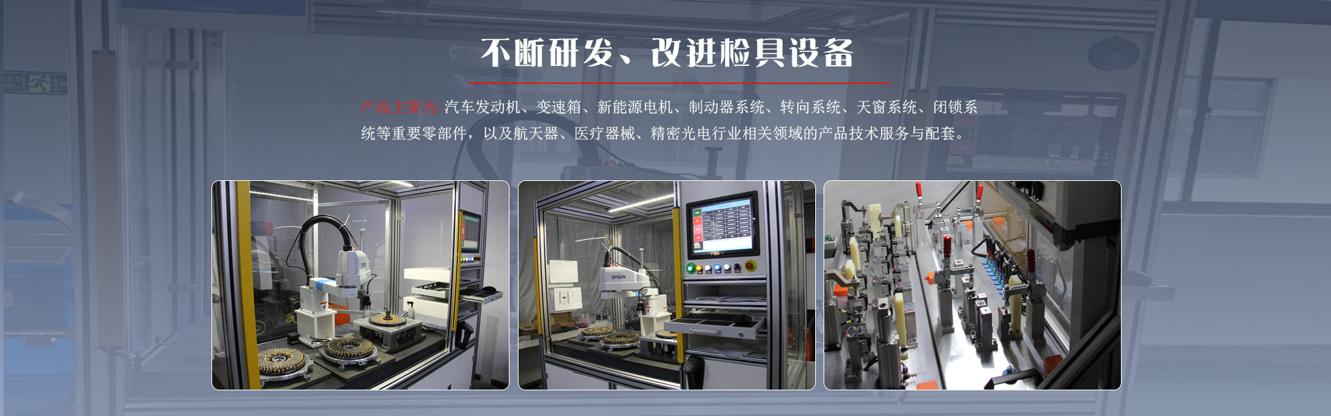
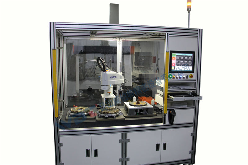
使钻头组件的尺寸,形状和位置更精确,更平滑。过度定位不仅对工件加工表面的位置和尺寸几乎没有影响,而且可以增加加工过程中的刚度。允许过度定位。可以由通用定位组件限制的自由度8、夹具和夹具的通用类型和精度。夹具对精度的要求很高,并且配合的类型也不同于普通机器。选择配合时,精度应由夹具零件确定。平均经济精度是基础,以确保夹具制造成本低。下表列出了夹具设计中常用的类型和精度:9、夹具,夹具,检具设计中标准零件的应用在夹具和夹具的设计中,我们经常使用螺母,螺栓,垫圈,圆柱销,锥形销,弹簧和其他紧固件。所有国家都有特定的标准。因此,它应该是设计时的首选,并学会检查标准。零件的波动系数安装在夹具中,并且在夹具中加工零件时,切屑可以顺利排出。固定装置必须考虑如何保持油和气源的位置。快速更换组件应考虑维护方便。 。是否有必要调整定位元件的位置(利用偏心元件的可靠性。夹具的强度和刚度应足以考虑零件毛坯的实际尺寸与图纸尺寸之间的偏差,并且卡的大小在一批空白中会引起液压或气动驱动器清洁的影响,请注意此问题,夹具应具有足够的强度和刚度,大多数11、型检查夹具以以下形式出现产品完整机器或组件功能测试台。
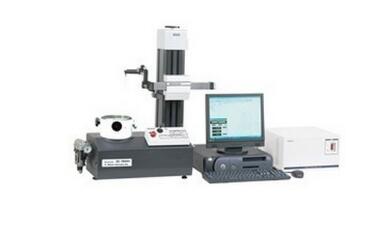
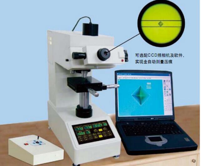
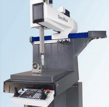
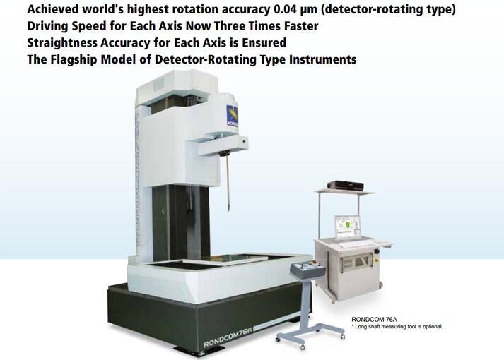
颜色测试模型,表面质量测试模型和各种测试夹具等。检具设计通用尺寸和形状检查工具广泛用于机械零件,冲压零件,焊接零件,注塑零件和零件的在线检查和检查。其他机械零件。常见的检查工具,例如非标准螺纹环规,各种类型的非标准合格规(塞规),各种曲面检测模板,R角度检测模板,角度检测模板,各种孔的塞规。使用前必须在扭矩检测器上校准扳手,并且检测范围扭矩数据将转换为百分表的刻度。常用的测量方法1.使用通用的测量工具,仪表,坐标测量机(CMM)等,它们是通用的测量方法,不属于检查工具的类别。2.使用平滑限位规(仅通过量规,塞规)和样品检查,非标准零件属于检查工具类别。3.检查夹具(包括测量支架)通常用于检查夹具。4.使用自动或半自动测量仪器,检查机等,其中非标准零件属于检查工具的类别。在什么情况下需要使用检查工具1.小批量,简单零件,低精度的常规测量工具。2.数量大,精度低,过程稳定,随机检查或简单的检查工具。3.数量大,精度低,过程不稳定和检查工具。4.需要大量,高精度,100%的检查和检查工具。 检具设计的五项原则:拥有并可以达到检验工具处理和测试的基准。 (包括加工基准和测量基准,可用于以后对检验工具进行修订和定期验证)。存在恒定且准确的定位基准,以确保检验工具的可重复性和可重复性。
低制造成本,耐磨性和稳定性。操作方便(包括产品的取放和检查,夹具操作,运输等)。在检具设计中,除了上述四个基本原理外,还必须考虑可以满足产品和过程质量的分析功能。例如:产品配合面,密封面,配合区域,对准面,孔/凹槽等。换句话说,检测功能符合产品质量控制要求。五、夹具设计案例介绍:车床夹具设计实例在“涡轮箱”零件加工过程中,为车床设计一种特殊的夹具。 二、定位计划和定位组件1。确定定位计划2。选择定位元件以选择角铁(角铁支撑表面消除了3个不确定度的工件),两个支撑钉(消除了2个不确定度的工件)和倒角的心轴(消除了1个不确定度的工件)。 三、夹紧平面图和夹紧装置的设计1.确定夹紧力的方向2.确定夹紧力的施加点3.夹紧力大小和夹紧方案的示意图四、设计1.定位装置(1)角铁(2)定位心轴)倒角的定位心轴与蜗轮孔之间有间隙配合。为确保安装平稳,并确保与中心轴的距离蜗杆孔相对于蜗轮孔中心轴的位置,减小定位误差,采用φ46H7/ g6的配合,即倒角芯轴的尺寸为φmm。此外,其轴线相对于夹具中心轴线的垂直公差不大于0.01mm。 00(3)支撑钉)两个支撑钉在夹具上的高度相同。位置不低于旋转中心(相对于角铁支撑板),并且两个支撑钉之间的距离应为尽可能大(分别靠近工件的两端)。
为了确保蜗杆孔的中心轴相对于端面N(144mm72mm)的垂直度,将两个支撑钉安装在夹具主体上后(请参见装配图),对它们进行加工。车床与夹具主体(汽车支撑钉的端面)一起,以确保其延伸长度的高度公差不大于0.01mm。 2.夹紧装置(1)夹紧机构采用螺丝夹紧机构。为使该机构简单,直接在定位心轴上加工螺纹。根据类推方法,选择M20螺纹以满足强度要求。([ 2)如图所示,压板和压板的结构,该夹具采用圆边压板,以确保压板的轮廓不超过工件的宽度,压板的边缘为压板侧面的开口可以方便快捷地在夹具上拆卸工件,夹具的尺寸应根据加工零件的尺寸,角铁的尺寸, 4.辅助设备(1)由于工件而产生的平衡重)夹具上的组件相对于工件的旋转轴不对称。机床主轴,即离心惯性力的合力不为零(ΣF=mrω20),因此要使其平衡,您需要添加平衡质量(即配重),以便使它产生的离心惯性力和原始质量产生的离心惯性力等于(2)保护罩。为了确保加工工件时的操作安全性,应设计一个保护罩。 5.定位。误差分析五、工程图夹具总图。 Drilling machine fixture design example. 一、 Clear design task. Design a drilling fixture with φ10 mm φ13mm on the lever arm part on the radial drilling machine.
1。 Parts drawing of lever arm 2. Analysis of lever arm processing technology (1) processing requirements processing technology The structure of the workpiece is relatively irregular, the arm rigidity is insufficient, the processing hole φ10 mm is located at the cantilever structure, and the hole accuracy and surface roughness are required to be high, so the process specification There are multiple processes of drilling, expanding, and reaming in the middle. Since the positional relationship of the two holes in this process is perpendicular to each other and not in the same plane, one hole needs to be drilled and turned 90 before drilling another hole, so design 二、 Positioning plan and positioning element 1. Determine positioning plan 2. Select positioning element 三、 Clamping plan and clamping device design Clamping mechanism四、 Fixture structure design 1. Positioning device ( 2) Adjustable support nails Adjustable support nails are selected from GB JB/T 8026.1-1999 (hexagon head support) M840-S. ([k3 5] Auxiliary screw support 2. Clamping device (1) M10 thread is selected for clamping to meet the strength requirements. (2) Open washer 3. Auxiliary device (1) Drill sleeve is selected from national standards. (2) Drill template 4. Clamping specific五、 Drawing fixture general drawing milling machine Fixture design example 一、 clarify the design task and design a special fixture for processing the keyway on the "sleeve" part on a milling machine. 1. Sleeve part diagram 2. Analysis of the processing technology of the workpiece (1) keyway width 6 mm by keyway milling cutter Guaranteed. (2) The symmetry of the symmetry plane on both sides of the groove to the φ45h6 axis0.05mm, parallelism0.10mm.
(3) Groove depth 8mm. 二、 Positioning plan and positioning element 1. Determine positioning plan 2. Select positioning element 三、 Clamping plan and clamping device design The clamping mechanism of the clamping mechanism Guiding and automatic release device四、 Fixture structure design 1. Positioning device fixed degree. Because it is a standard part, it can be found in the relevant national standards or industry standards. The JB/T8018.1 in this fixture -1999 Select "V 24JB/T 8018.1-1999". (2) Support sleeve 2. Clamping device (1) eccentric wheel (2) eccentric wheel bracket 3. Auxiliary device (2) orientation In order to ensure the correct position of the clamp on the machine tool, an orientation key should be set at the bottom of the clamp. The orientation key has been standardized and can be selected directly from JB/T8017-1999. 4. Clamp specific五、 Draw fixture general drawing 1-clamp Concrete 2—Cylindrical pin shaft 3—Eccentric wheel bracket 4—Eccentric wheel 5—Activity V Right-angle hook torsion spring installer 1 Handle material: 45 Head heat treatment: HRC=42~48 Right-angle hook card slot Right-angle hook card slot can be cut by wire Machining or electric pulse processing or milling out as shown in the picture (as shown in the picture) to ensure the slot width size, and then using plug welding (three-point) to weld an iron sheet with the same shape as the milled part. The inclined surface of the right-angle hook groove is clamped by the head groove of the torsion spring installer with pliers, and the torsion spring head is moved until it reaches the assembly position. Torsion spring installer 2 Pay attention to head design pay attention to head design pay attention to head design attention Head design The processing method of the head like torsion spring installer 2 is similar to torsion spring installer 1, and the processing method is similar to torsion spring installer 1.
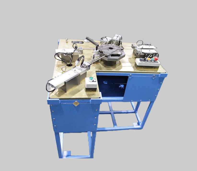
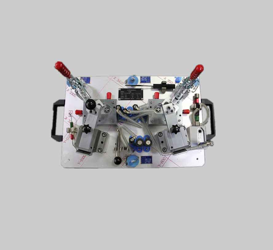
The non-standard torque wrench punches a hole at the top and fits the appropriate nails to achieve the torque of the wrench. The figure above is a schematic diagram of a non-standard torque wrench. The diameter of the compression spring wire is changed while keeping the inner diameter of the compression spring changed. , Will change the torque of the wrench. The wrench can be regarded as a non-standard special assembly tool and put into the production line when the screw assembly has torque requirements. After being checked by the torque tester, the wrench can be regarded as a special inspection tool when used to measure the screw assembly torque. Button life test bench (functional special tooling) This test bench is specially designed for the life test of product buttons. In a sense, this tooling can also be regarded as a checking tool. Panel Mounting Base Motor Button Tooling Installation and Working Principle1、 Install the panel mounting base, contact rod seat assembly, and slider seat assembly to the bottom plate of the button test bench.2、Then install the motor assembly and cam seat assembly in place, but do not tighten the screw3、to install the panel on the panel mounting base (note that the button is vertically downward), and press it with the panel mounting pressure plate (be careful not to use force to avoid Crush the panel).4、 Adjust the position of the panel and the touch rod assembly until the hard rubber head of the touch rod is aligned with the button to be tested and slightly touched, then tighten the pressure plate screw of the panel to complete the positioning of the panel. At the same time, tighten the set screws on the mounting base of the contact rod seat assembly to complete the positioning of the contact rod mounting seat assembly (check whether the contact rod is flexible). 5、 Tighten the mounting screws of the slider base assembly, push the slider from back to front, until the front of the slider and the back end of the button lever is attached, and keep it still.6、 Move the cam assembly to adjust the distance between the cam assembly and the slider assembly to obtain a reasonable stroke required for the cam to rotate one circle and the touch rod to press the button. After adjustment, tighten the cam seat assembly mounting screws.
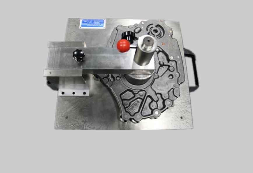
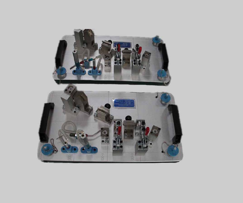
7、Install the motor assembly and the connecting shaft to complete the mechanical connection between the motor assembly and the cam assembly. 8、 Turn on the power supply and adjust the motor speed to reach the requirement of 120 revolutions per minute, so as to achieve the design index of pressing the button 120 times per minute. 9、 Movement principle of the test bench: Motor rotation, cam rotation (upper half circle), the slider moves forward, the button lever moves forward, and the button is pressed down to complete an effective press. Motor rotation Cam rotation (lower half circle) The button contact rod resets under the action of the spring. The slider resets and the button resets. Button: There are five pressing points up, down, left, and right, and the center. Welding tooling welded workpieces. Welding parts on the tooling. This is the workpiece on the tooling. The basic material of the tooling is cast aluminum, partly reinforced by steel plates. Polyurethane rubber indenter Steel (threaded) reinforcement plate 检具设计 Case The inner side of the tooling during inspection. The condition of the inspection rod tooling during inspection. The inspection tool above is used to detect the relative position of each important surface of the part. The inspection standard is OK if it passes successfully, otherwise it is NG. The tooling is made of cast aluminum (ageing) as the basic material, the shaft sleeve is made of brass or tin bronze, the detection shaft material is 45 steel, heat treatment: HRC=42-46 Concluding remarks The tooling fixture 检具设计, this is a big topic , It should be divided into three parts to explain, but considering that the technical basis of the design of these three parts is the same, that is, a certain basis for the design of mechanical parts, preliminary experience in ordinary mechanical processing methods, and a certain understanding of heat treatment surface treatment processes. Preliminary design benchmarks, process benchmarks, inspection benchmarks and six-point positioning concepts, have a good understanding of commonly used measuring tools and measurement methods, have preliminary contact and use experience with some simple tooling and fixture inspection, and have the hands-on ability of a junior fitter. With the above foundation, I think I can try to design tooling fixtures. This lecture talks about design ideas, technical foundations and some case introductions, just trying to bring young friends who are interested in tooling 检具设计 into tooling fixtures 检具设计 It is only the door, and it is inevitable that there are all things missing. Therefore, it cannot cover the world. The so-called "master leads the door and practice on your own." Please understand if you are disappointed. Part of the information in this article comes from the Internet, thank you


")
")
")