
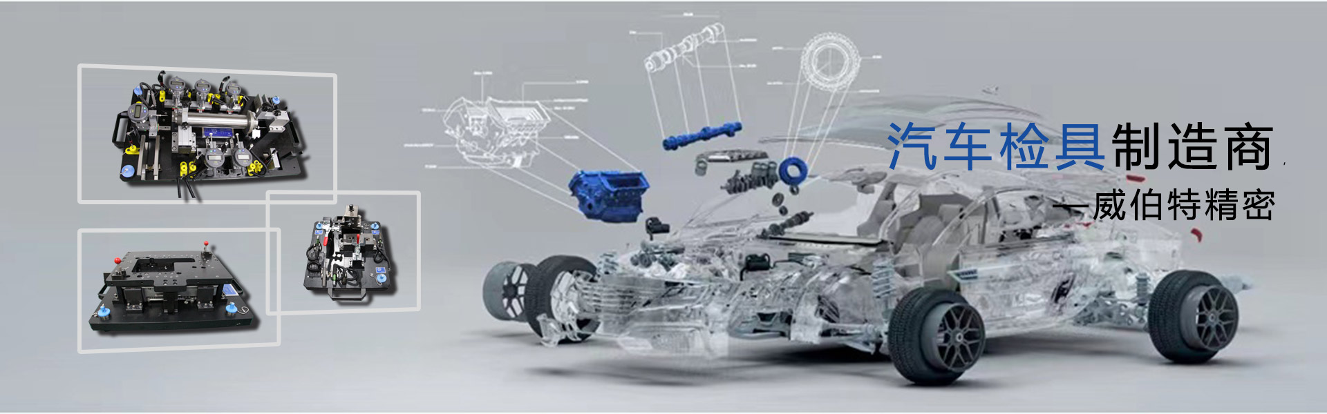
专业管理|汽车检具设计(系统信息)(集合)-由IASC-CN特别提供
注意:本文相对较长且专业,阅读时间超过30分钟,请合理安排您的时间
机械系统的坚固设计
稳健性也变得健壮,这是指因数(原因)条件发生微小变化对因变量(结果)不敏感,例如产品性能对所用材料的劣化不敏感,在某些情况下,使用便宜或低等级的材料会使产品对制造尺寸的敏感性降低,从而可以改善产品的可制造性并降低制造成本。例如,使产品对使用环境的变化不太敏感。为了确保产品的可靠性并降低运营成本,根据此指导思想,将产品性能,质量和成本综合考虑,做出最佳设计,不仅可以提高产品质量,还可以降低成本。这种工程设计方法称为“稳健设计”
健壮的设计方法是在过去的二十年中迅速发展起来的一种新方法,可以有效地保证产品质量。该方法目前受到高度重视,并在许多工业化国家广泛使用。健壮设计的基本概念是:设计变量和噪声因子的变化将被转移到设计函数中,从而导致质量指标和约束条件恶化,并且变化的统计分布也将影响设计的概率和统计特性。设计功能。健壮设计的核心是优化设计问题,该问题要求在满足约束的同时实现健壮产品质量的目标。
汽车检具设计的基本原理
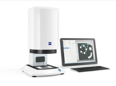
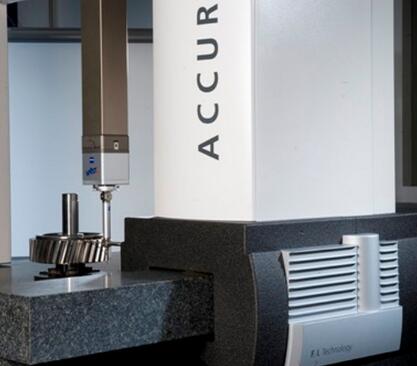
汽车零件具有许多复杂的形状,而传统的测量方法则无法检测出不规则的形状。汽车检具汽车检具上模拟块的形状,尺寸和位置要求很高的制造要求,有时需要精确到0.05mm甚至更高的要求,因此汽车检具必须执行三坐标测量以确保其准确性要求合格,并且要求专业设计师进行设计。
各种汽车零件,专用性强,大多数汽车检具属于非标设备,一般根据测试内容和产品结构特点,公司的生产条件和实际需要以及特殊设计,设计质量检验工具,生产效率,产品质量,开发周期,加工等都有直接影响。事实表明,通过使用合理设计的检查工具进行在线检查,可以满足图纸尺寸要求,操作方便,实用性强。它可以有效地保证产品的质量,并且极大地提高了劳动生产率,为此设计汽车检具必须考虑几个方面的基本要求和基本原理
一种处理原理
汽车检具不仅必须具有更好的性能,而且还要确保组装过程的要求,同时力争使其结构简单,重量轻,操作过程中动作迅速且易于制造。
可制造性原则意味着设计的检查工具可以满足以下产品的组装和测试要求
1汽车零件通常由单个或多个零件组成。一些检查工具具有异常复杂的结构和各种操作顺序。目前,人工检查零件很多,设计时预留了一定的操作空间。
2内部零件的检查具有一定程度的塑性变形。在将定位器和夹具设置在检查工具的设计上时,应充分考虑产品的变形区域和方向
3作为一种高精度设备,检查工具对生产环境有一定要求。生产车间不可避免地会产生烟雾,金属或废物,这将损坏检查工具裸露的光滑工作表面,并需要进行覆盖和采取其他措施。
两条经济原则
在清晰的生产程序的前提下,分析产品测试的内容,然后根据产品的批次大小制定检具设计计划。实际的焊接工具必须很复杂。根据工件的具体情况,有必要推广小型检查工具的效果,并带来很大的好处。
例如,可以将某些工具设计为仅用于工件定位,并且其任务是将工件固定在指定位置而无需夹紧工件。检查时,只需要将工件放入检查工具中,如果可以插入,就可以判定产品合格。这种工装不仅可以满足检验要求,而且可以提高生产效率并最大程度地减少加工操作的复杂性。
此外,在执行检具设计时,我们应尽最大努力考虑使用通用的标准化组件,并使它们与特定的检查有机地结合在一起。这种设计方法可以灵活运用,可以简化检查工具,降低检查工具的生产成本,缩短加工周期,也可以保证检查工具的生产进度。如果可能,尝试设计常规检查夹具,组合检查夹具或柔性检查夹具。这些检查夹具无需调整或略微调整,适合于组装和检查类似类型的工件。
根据产品生产计划,如果是批量生产,则可以将现有设备略微更改为用于特定结构零件的专用机器,并可以获得显着的经济效益。如有必要,可以使用机械检查和自动检查。可以大大提高检测技术水平,从而提高企业的生产竞争力。
三个可靠性原则
可靠性是指产品在指定时间内和给定条件下完成指定功能的能力。它不仅直接反映了产品每个组件的质量,而且还影响了整个产品的质量和性能。可靠性分为固有可靠性,使用可靠性和环境适应性。可靠性指标通常包括可靠性,无故障率和故障率。
检查工具必须具有安装可靠性,以确保在检查工具的使用期内所有受压部件都应具有足够的强度和刚度,并且操作位置必须设置在易于工人接近的位置确保生产安全。
1检查工具可靠性设计过程中应遵循的原则
1)可靠性设计应具有明确的可靠性指标和可靠性评估计划
2)可靠性设计必须贯穿功能设计的各个方面。在满足基本功能的同时,必须充分考虑影响可靠性的各种因素。
3)故障模式(即系统,组件,组件故障或故障的表现)应设计为最大程度地消除或控制产品生命周期中可能发生的故障(故障)模式。
4)在设计时,我们应该在继承以往成功经验的基础上,积极采用先进的设计原理和可靠性设计技术。但是在采用新技术,新组件,新工艺和新材料之前,必须先进行实验并严格证明其对可靠性的影响。
5)在设计产品可靠性时,应权衡产品的性能,可靠性,成本,时间和其他因素,以便制定最佳的设计方案。
2.检查工具可靠性设计的主要内容
1)建立可靠性模型以预测和分配可靠性指标。在产品设计阶段,应该多次重复可靠性指标的预测和分配。随着技术设计,建模和可靠性指标分配的不断深入和成熟,设计也应不断进行修改和改进
2)进行各种可靠性分析,例如故障模式影响和危机分析,故障树分析,以查找和确定薄弱环节,并在发现隐患后改进设计以消除隐患和薄弱环节
3)采用各种有效的可靠性设计方法,例如制定和实施可靠性设计标准,降额设计,简单设计,耐环境设计等,并将这些可靠性设计方法与产品性能设计工作相结合。产品的故障率,最终达到可靠性要求。
四个艺术原则
要求检具设计具有美观的外观,以使操作员在身体和心理上感觉舒展,并在功能使用和经济允许的条件下给人们带来美好的享受。造型的美法则包括形式的美法,例如变化与统一,平衡与稳定性,比例与比例,对比与协调等。整合了多种美学因素的美学原理也是适应现代的美学原理。工业与科学技术。
造型设计的原则:实用性至上,美学处于从属地位,经济是制约因素,工业品造型设计必须首先满足实用功能,设计的质量不是由设计师来判断,而是由用户来判断评价:一旦工业产品失去其使用功能,其艺术价值也将丧失。但是,使用功能和艺术造型不应该对立。两者在辩证法上是统一的。功能决定形状,形状表示功能,但是形状既不简单,功能部件的组合不是杂乱的堆叠,而是基于人机系统的协调。通过使用一般的造型艺术规则和建模美容规则来精炼和塑造外观,以使功能更合理且形状恰到好处。
检具设计的基本步骤
汽车检具的设计过程也非常复杂。如果要设计合适的汽车检具,则必须考虑影响它的许多因素以及许多相互依赖的参数。如果不了解它们之间的相互依赖性,就不可能描述整个设计过程。描述过程的基本要素是描述设计,制造和使用的三个主要技术环节。如图所示,该图显示了检具设计,系统的各个因素之间的相互关系,从检查工具的概念到检查工具的完成,图中显示了检查工具系统的设计过程。
技术人员应根据生产需要执行以下步骤检具设计
一)明确设计要求,认真调查研究并收集设计数据
获得检具设计的任务后,技术人员应首先根据任务书中建议的任务设计检查工具的结构。在设计检查工具的结构之前,必须明确设计要求,认真研究和研究,并收集设计数据。请执行以下操作:
(1)认真研究零件图,技术要求以及产品的详细检查内容
(2)了解零件的生产量,生产节奏和频率以及其他相关信息,
(3)了解零件的工艺规定和该工艺的具体技术要求
(4)了解公司的生产条件和技术状态以及检验工具的制造和使用
(5)准备用于设计检验工具的各种标准文档,工艺规程,典型检验工具的目录以及相关检验工具的设计指导材料
(6)收集国内外相同类型检查工具的相关设计和制造数据,并吸收可以结合实际情况使用的先进合理零件。
此外,根据设计需要,您可以前往市场,类似的工厂,用户和科学技术情报部门进行研究并收集相关的技术数据。技术数据包括检验工具零件标准,检验工具结构图,样品,图片等信息。此外,有必要与客户检查工具工程师和产品质量工程师仔细沟通以征求他们的意见,以免造成弯路,并避免以后的设计计划与客户要求不一致或需要进行重大更改。
二)确定检查工具的总体结构
在上述调查研究和数据综合分析的基础上,必须起草检验工具的设计计划。必须构思和选择以下内容:
1)车间的机械化和自动化程度
2)通用性,即确定其应用范围以及是否可扩展
3)用于实现特定功能的原理和相应的机制,例如定位和夹紧方法和机制,检测方法和机制
4)检查工具的基本组成和总体布局,主要是零件的组合
通常会提出不同的方案,从技术和经济两个方面进行论证,然后选择理想的方案
根据检具设计的一般原理,检查工具的结构设计可以大致分为以下解决方案:
(1)确定定位计划(2)确定夹紧计划(3)确定产品放置计划(4)确定底板的类型,材料和热处理(5)确定检查计划(6)确定处理设备
三)绘制检查工具图案
绘制检查工具的装配图
四)绘制检查工具的零件图主要是绘制检查工具中非标准零件的工作图。拆卸和绘制零件图的顺序与绘制总装配图的顺序相同。每个零件必须在标准图纸上分别绘制,尝试使用1:1的比例,从第一个角度投影图片,并按照国家图纸标准进行绘制。除了绘制图形外,还应标出尺寸和公差,表面粗糙度,形状公差,材料,热处理和其他技术要求。
五)校对
对所有零件图和总图进行校对,从图形,尺寸,准确性,技术要求等方面检查正确性和合理性,以使零件图和总图充分协调。
六)图纸检查工具数据
包括量具测量计划图,操作说明,MSA
检具设计还有另一个重点。它必须符合人体工程学。作为一种测试设备,检查工具需要由工人操作,因此设计必须符合工人的操作习惯,以使检查工具更加实用,坚守一线。
设计过程中的人机工程学
人机工程学是将人,设备和环境视为一个系统,利用生理,心理学,机械等相关学科知识,根据人和机器的条件和特点,合理分配人和机器的操作功能,并使他们彼此适应,从而为人们创造一个舒适安全的工作环境,以优化工作效率。
设计时要考虑的主要因素是人体大小,人体力学,对各种信息做出反应的敏捷性等。人体工程学中设定的标准是机器和人体的大小,形状和力是否匹配。 ,该机器是否光滑,使用方便,是否可以防止因操作过程中用户误操作而造成的意外伤害和危险。每个操作单元是否实用,每个组件是否布置得毫无疑问地被认可,易于清洁,维护和维修。
在具体设计中反映出,有必要合理选择操作姿势。常见的操作姿势是站立和坐着。站立姿势活动范围大,容易施加力。但是,需要精确观察和阅读的工作和活动范围很小。对于手动操作,请选择坐姿。工作台的高度应根据人才比例来设置。站立姿势的工作台高度为人体高度的10/19(通常为800mm),坐姿的高度为7/17.
在设计手柄时,请注意手柄操作所需的力和手的移动范围不应太大,并且手柄的形状应便于操作和施力。
产品的取放应考虑正确的手动习惯。通常,左手进行辅助活动,而主力在右手。因此,检查工具的结构必须具有合理的移动空间,以利于右手操作。
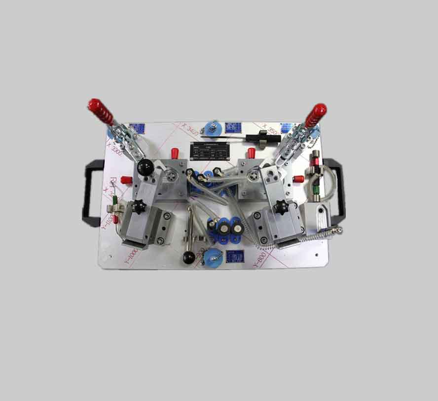
检查夹具的人体工程学
1.考虑到所有检查工具的正常手柄检具设计,坚固耐用的外形
2.尽可能使用以防止意外冲击损坏检查工具的零件
3.当转臂过长时,考虑到操作的安全性,请添加一个限位销和一个缓冲装置,以避免潜在的安全隐患
4.有两个或多个相邻的旋转机构,在设计时,旋转托架必须处于相同的方向和水平状态(或90度的增量偏转),测量时应确保旋转机构高度相同且车削中心与仿真块连接的情况下,旋转中心应低于仿真块的最低点,以避免干扰零件
汽车检具的设计要求
好的汽车检具必须满足以下基本要求:
1)为了确保对汽车零件质量的有效判断,保证汽车零件质量是否合格的关键首先是要根据以下情况正确选择定位基准,定位方法和定位零件产品图纸,必要时还根据积累的经验分析定位是否合理,以使其具有恒定且准确的定位基准,以确保最大的可重复性和线性度。还必须注意检查装置中其他机构对检测功能的影响。注意检查夹具应具有足够的刚性。反复使用的检查工具还应注意相关部件的强度和耐磨性,以确保检查工具的使用寿命。
2)检查工具应符合生产率的要求。专用检查工具的复杂性应与生产程序兼容。应尽可能采用各种快速高效的安装机制,以确保操作便利,缩短辅助时间并提高生产率
3)良好的过程性能。专用检查工具的结构力求简单合理,以方便制造,组装,调整,检查和维护。专用检查工具的制造属于单件生产。通过调整或修理保证最终精度时,检查工具应配备便于调整和修理的结构
4)表现良好。专用检验工具的操作应简单(包括产品的抽检,夹具的操作和搬运),省力,安全可靠。如果在客观条件下允许并在经济上可行,则应尽可能使用气动,液压和其他机械化夹紧装置,以减轻操作员的劳动强度。
5)有必要适当提高检查工具组件的通用性和标准化程度,并选择标准化的组件,特别是商业标准组件,以缩短检查工具的制造周期并降低检查工具的成本。
标准零件的选择原则:
在检查工具的结构设计过程中,为了节省建模时间并缩短后续制造周期,有必要选择合理的标准零件进行设计。使用标准零件不仅必须满足检查工具的功能要求,而且还必须更简单,更轻便。 ,并且还满足以下要求
1.尽可能使用检具设计中OEM推广的标准零件。通常,像大众汽车一样,一般的OEM也有指定的标准零件。这是接受的标准条件之一。
2. 检具设计在使用尽可能多的模块的过程中,但更主张提出新的结构设计和构想,例如针规量规,L形翻盖支撑,复制机构,滑动机构,弹性检测等。
3.内饰和外饰采用标准的铸铝地板:车身部件根据客户要求或零件要求采用钢焊接地板(需要两次回火)
4.如果客户未指定标准零件,则可以按照流行的标准来实施,从而适当简化零件的结构并提高加工效率
在检具设计中,除了四个基本要求外,我们还必须考虑可以满足产品和过程质量的分析功能。例如:产品的装配面,密封面,配合面积,对准面,孔/槽等检查工具功能应符合产品质量要求。
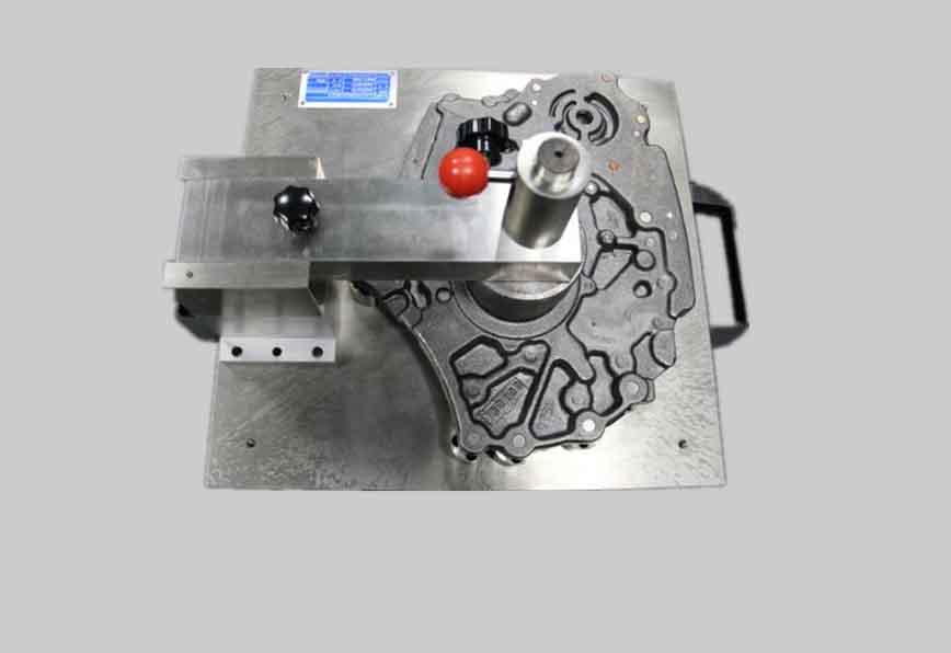
检查工具的制作原则:原则上,根据零件的特性进行制作,尝试使用凸面检查,见图,制作时要考虑的要点:
在检查零件时很容易确定精度方向;考虑到成品内部和外部的变形,很容易拾取零件而不会产生干扰方向;尝试使用加载位置,该位置可以与相对加载位置结合使用,例如被测零件和使用测量工具。必须将偏差作为增量为90的相位偏差。每个匹配零件的检查工具的制造方向应尽可能一致,以便于问题分析。
检具设计概念确认
通常,重要零件的检查工具计划需要由OEM批准。在开始设计之前,应举行设计概念的初步会议。应该参加的主要人员是:供应商检查工具工程师检具设计和制造商的代表。
设计概念应包括详细的检查工具草图和书面说明,以便能够进行检具设计。设计概念不必像完整的设计那样详细,而应包括以下信息。
1)被测零件和检查工具的底座之间的位置关系最好使用装载装置,但是,其他位置可能更适合被测零件检查工具的使用(即首次使用位置)。如果位置太高,则应以90度的增量偏转。
2)定位基准面应与几何和公差图一致,并且可以使用随附的基准垫
3)支持被测零件的检查工具和设备
4)检查夹具零件和设备以测试以下功能
5)关键产品特征(KPC)产品质量特征(PQC)过程监控点(PMP)
6)所使用的材料应基于检查工具的用途和环境,以确保在当前生产的有效期内零件的功能,可重复性和线性。匹配或相邻零件的轮廓形状或线条特征(如果适用)
7)设计概念应考虑操作员的人体工程学,被测零件的组装和拆卸简便性,三坐标检查和SPC数据收集的可行性。当检查工具用于全球集成时在汽车项目中,应考虑操作员的习惯(使用区域语言)
8)基准测试选择
尝试选择零件重心的方向作为主基准平面,以方便零件的稳定放置
在基准总数尽可能少的前提下,使用3个或更多点作为主基准平面以确保零件的稳定性。
所有主基准必须具有相同的特征
选择第二个和第三个基准平面的顺序
选择4方向销钉作为孔位置,选择2方向销钉作为插槽位置。插槽的方向必须平行于第二参考平面
选择两个2方向引脚作为插槽位置,两个平行的插槽必须平行于第二参考平面,另一点必须位于第三参考平面上
选择4通销作为孔定位,在轮廓或外围上另选1个点
在第二个基准平面上选择2个点,在第三个基准平面上选择1个点
六点定位原理
在检查操作中,首先应将工件确定在检查工具中的位置。并且在测量和检测过程中,它一直保持在其原始位置,根据图纸要求确定工件位置的过程称为定位。在检查过程中将工件保持在特定位置的过程称为夹紧。
为了获得工件在检查工具中的所需位置,我们首先应该研究如何确定物体在空间中的位置。未定位的工件的位置不确定。确定性称为自由度。
如图所示,将未定位的工件放置在空间直角坐标系中,并使用X,Y,Z三个相互垂直的坐标轴来描述工件位置的不确定性。矩形平行六面体可以沿X,Y和Z轴移动,并且可以绕XYZ轴自由旋转,共有六个自由度。
正确放置工件必须首先限制工件的自由度。消除这六个自由度后,就可以完全确定物体在空间中的位置,因此自由度也是确定物体空间位置的独立参数。
如图所示检具设计,如果将板B放置在XOY面上以支撑对象A,则对象A只能沿OX轴和OY轴移动,并绕OZ轴在此平面上旋转,但不要沿OZ轴移动并绕OX轴和Oy轴旋转,否则对象A将离开板B。这意味着支撑板B消除了对象A的三个自由度。如果将图2所示的对象放置在对象A的xoz平面上,则对象A不能沿OY轴移动并不能绕OZ轴旋转。消除了两个自由度。
最后,只要在物体A的ZOY平面上设置挡块3以消除物体沿OX轴的移动自由度,就可以确定物体A的空间位置。
根据几何,我们知道3个点可以确定一个平面。您可以使用三个定位支撑点4、5和6来替换图中的支撑板B,同时将挡块1、2和3用作定位支撑点。因此,定位支撑点平均消除了一个自由度。因此,对象的空间位置需要六个根据图纸排列的支撑点,以消除对象运动的六个自由度。这受到适当分布的六个支撑点的限制。工件六自由度的原理称为六点定位原理
从图中可以看出,三个支撑点在XOY平面上,两个支撑点在XOZ平面上,一个支撑点在ZOY平面上
打开
,具有三个支撑点的平面称为安装基础表面。支撑点的分布必须适当,否则六个支撑点不能限制工件的六个自由度。在此表面上,三个支撑点不能在一条直线上。 , The center of gravity of the supported workpiece must fall within the triangle formed by these three supporting points as the vertices. The farther the distance between the three positioning supporting points, the larger the installation base surface, and the stability and correlation of the workpiece installation The higher the position accuracy, therefore, the surface with the largest contour size of the workpiece should be selected to contact the mounting base surface.
The plane with two positioning support points is called the guide base surface. The connection line of these two support points should be parallel to the installation base surface, and the greater the distance between the two points, the better the installation accuracy. Therefore, the surface with the longest dimension of the workpiece should be selected to contact the guide base surface. The plane with a positioning support point is called the fixed-range base surface. Obviously, installing a positioning support point does not require a large area and length, so the workpiece is usually selected The smaller surface is in contact with the fixed base surface.
The positioning method of the second workpiece in the inspection tool
As mentioned above, in the inspection operation, the process of obtaining the determined position of the workpiece in the inspection tool according to the requirements of the drawing is called positioning. To obtain the determined position of the workpiece in the inspection tool, the six-point positioning principle of object positioning must be followed.
Analysis of constraints in product positioning
检具设计In the initial stage, the positioning system of the product drawing must be analyzed first. The stability of the positioning system will not only affect the production and assembly of the product, but also may affect the measurement results of the parts during the later use of the inspection tool. Stable
Using the six-point positioning principle can analyze and judge whether the positioning structure in the inspection tool is correct, whether the layout is reasonable, and whether the constraint conditions are satisfied.
According to the constraints of the degree of freedom of the workpiece, the positioning of the workpiece can be divided into the following types
1) Complete positioning Complete positioning refers to the positioning where the six degrees of freedom of the workpiece are not repetitively constrained. When the workpiece is in the X, Y, and Z coordinate directions, there are dimensional requirements or position accuracy requirements.
2) Incomplete positioning The number of restricted degrees of freedom of the workpiece is less than six
3) Under-positioning
4) Over-positioning The positioning state where the positioning component repeatedly restricts the direction of the product with the same degree of freedom is called over-positioning. Whether this positioning status is allowed to be used is mainly judged from its consequences. When over-positioning causes product deformation or interference between the product and positioning components, it will obviously affect the placement state of the product, and over-positioning cannot be used.
There are generally two ways to eliminate or reduce the interference caused by over-positioning; one is to change the structure of the positioning element, such as shrinking the setting
Typical 3-2-1 positioning principle in inspection tools
The automobile industry is one of the pillar industries of various industrialized developed countries. As one of the important parts of the automobile structure, 检具设计 is the main reason for the quality of the automobile body. According to the statistics of the US automobile industry, 72% of the body error comes from the positioning error of the welding fixture.
Automobile bodies are mainly assembled from many stamped parts. Thin-walled parts account for more than 70% of the body-in-white assembly. Due to the poor rigidity of thin-walled panels, they are easily deformed, and they are usually used in the inspection process. Point positioning and clamping to ensure the fitting of each part at the welding position. Due to the greater flexibility of the thin wall, it is easy to deform under processing load. A better positioning system has a great influence on the stability of parts.
For the positioning of the positioning surface 1-3, try to ensure that the positioning block is perpendicular to the plane of the support. When the positioning block cannot be guaranteed to be perpendicular to the sheet metal plane, the sheet metal positioning block is allowed to be at a small angle. In theory, 3 positioning surfaces can be used to position one surface. When using 3 positioning surfaces for sheet metal parts, the sheet metal parts may not be placed smoothly. Therefore, auxiliary positioning surfaces are sometimes added to ensure the stable placement of the sheet metal parts. When there is no clamping device within 350mm, the product will shake when placed, so it is necessary to add a clamping device to place the product to prevent the product from shaking, or there is a gap between the theoretical positioning surface, and the measurement result is inaccurate during detection. 。 To sum up the above two points, in actual production, large sheet metal parts and complex plastic parts have more than 3 positioning surfaces, but 4 or more. This situation is over-positioning, but this is allowed.
3-2-1 The positioning principle is the most basic condition for limiting the six degrees of freedom of a product in space. According to the characteristics of the part, over-positioning beyond the 3-2-1 principle is allowed on汽车检具 to ensure the positioning of the part. The reliability.
The typical positioning method of the 3-2-1 principle is as follows
3-2-1 The principle of positioning means that there are 3 positioning surfaces, 2 positioning holes, and the center of the positioning hole is connected to form a line. This positioning principle is commonly used.
3-2-1 Positioning principle: 3-2-1 Positioning principle is the most basic condition that restricts the six degrees of freedom of a product in space. According to the characteristics of the parts, it is allowed to exceed the 3-2-1 principle on the inspection tool. To ensure the reliability of positioning in another case, the three positioning surfaces control the direction of the maximum projection surface of the product, the connection of the two centers controls the vertical direction and rotation of the product, and the four-position positioning pin (hole) controls the left and right direction of the product, in turn That is, the 3-2-1. datum A first constrains three degrees of freedom, then adds a datum B to constrain it with 2 degrees of freedom, and then a datum C to constrain one degree of freedom.
The positioning of the product in the inspection tool
In the assembly process, the process of determining the mutual position of the parts to be installed and the parts is called positioning. The usual method is to analyze and determine the positioning datum according to the product drawing, and then consider its corresponding production requirements. Positioning method.
Scribing positioning is the original method of positioning, which is time-consuming and labor-intensive, and has low accuracy. It is only used when single-piece production and low accuracy requirements are required. During the assembly of inspection tools, positioning components are often used for positioning, which is fast and accurate , Positioning element is a device used to limit the position of the product on the inspection tool, such as positioning block, positioning pin, profiling surface, etc. They must be accurately arranged on the inspection tool according to the positioning principle, product positioning datum and process requirements in advance, and then each installed part is placed in a certain order at the specified position of the positioning element (contact with each other) to complete positioning.
1) Selection of positioning datum The basis for determining the position and size is called datum, which can be point, line, or surface. According to the purpose, it can be divided into design reference and process reference. Process reference is further divided into positioning reference, assembly reference and measurement reference. According to the positioning principle, the positioning reference is divided into main positioning reference, auxiliary positioning reference, auxiliary positioning reference and so on. When positioning on the inspection tool, the positioning reference of the product must be in contact with or coincide with the positioning component on the inspection tool. Correctly selecting the positioning reference of the product can obtain accurate, stable and reliable positioning, and also affect the entire assembly, measurement and检具设计Confirmation of the structure scheme
The importance of benchmarks
The result of the size report of a part measured by three-coordinate measurement is OK, but the result of inspection by the inspection tool is NG, or the state of the part tested by the inspection tool is OK, but the result of the three-dimensional measurement of the part is NG Yes, in this case, it is impossible to determine whether the parts are qualified. For this kind of problem, we will sort out the following steps;
First of all, it is necessary to check whether the measurement datum selected by the three coordinates is exactly the same as the positioning datum selected by the inspection tool when measuring parts. In most cases, the problem can be basically solved by analyzing this point.
Secondly, if the benchmarks are consistent, check whether the inspection size of the inspection tool meets the requirements of the drawing
Again, if all the above meet the requirements, then you need to measure the parts again to investigate the repeatability of the part measurement. If the result is not significantly different from the first one, it means there is a problem with the inspection tool, and it may be inspected. Has expired, and the accuracy has changed.
When selecting and designing positioning components, it is necessary to consider adapting to the conditions of the product positioning datum. The shape of the product is diverse, but their basic structure is composed of flat, cylindrical, conical and Composed of various forming surfaces, these surfaces may be selected as positioning references. Therefore, corresponding positioning elements can be selected or designed according to positioning references of different shapes.


")
")
")